Storage structures for liquid dairy waste range from low-cost earthen basins and moderate-cost concrete pits and tanks to higher-cost, glass-lined steel tanks. This publication deals with earthen pits, with and without concrete liners. Earthen pits (basins) may be located above, below, or partially below grade. Below-grade pits are easy to fill by scraping, whereas above-grade pits may require pumps for filling. Open-storage structures should be located to minimize odor complaints and sight nuisances, but they should be located as convenient to the source of waste and polluted runoff as practical. Open pits should be fenced, as necessary, to exclude animals and children.
Earthen pits
Earthen pits (also known as waste storage ponds or basins) are usually constructed by excavation and forming earth berms, and thus are partially below and partially above the original grade. Berms help to shield the contents from view and to exclude surface runoff. Earthen pits are built similar to lagoons, but with less capacity and do not provide for significant dilution or biological treatment. They must be designed and constructed to prevent ground and surface water contamination. To be approved by the Missouri Department of Natural Resources (Missouri DNR) and the Natural Resources Conservation Service (NRCS) for cost-sharing by the Agricultural Stabilization and Conservation Service (ASCS), earthen pits must have a suitable clay liner compacted by three passes of a sheepsfoot roller. The thickness of the clay lining depends on the geologic rating and the depth of waste in the pit.
Location requirements
The Missouri DNR requires that an earthen pit be at least 100 feet from a well and recommends that it be at least 300 feet. If plans include an earthen pit 100 to 300 feet from the water supply, a favorable report must be obtained from the Missouri Division of Geology and Land Survey. The State Milk Board will not permit earthen pits to be closer than 100 feet from the water supply on Grade A dairy farms.
In some situations, especially in southern Missouri, location may be dictated by soil and geological considerations. Try to avoid a site where the bottom of the pit will be close to limestone, depending on soil type (permeability).
Soils investigation
For economical construction of an earthen pit (without requiring the use of soil amendments, an artificial liner or hauling a suitable clay soil from a remote location for sealing the pit), a suitable clay soil is a requirement. An ideal soil for a pit would have at least 30 percent fines content. The block-structured red clay soils of southwest Missouri are not well suited for sealing a pit and may require use of an amendment, such as bentonite or soda ash, to provide an acceptable seal. Natural Resources Conservation Service (NRCS) County Soil Surveys may be used as a source of information for preliminary screening of an area for suitable sites. A soils investigation to the depth of the proposed pit with a backhoe excavation or soil borings at the site is standard procedure in verifying a suitable location.
For a cost-shared earthen pit, a soils investigation by the NRCS, or a soils consultant, is required. Only soils that fall within the Unified Soil Classification System designations of CH (clays of high plasticity), CL (clays of low to medium plasticity — gravelly, sandy or silty clays), GC (clayey gravels — gravel-sand-clay mixtures) and SC (clayey sands — sand-clay mixtures) will be considered by the Natural Resources Conservation Service (NRCS) for clay pit liners.
Geological requirements
For cost-shared earthen pits and/or for a letter of approval from the Missouri DNR, a geological report on the proposed pit site from Missouri DNR's Division of Geology and Land Survey is required. If the site is:
- In an area with karst terrain
- Rated as having a severe collapse potential, an earthen pit will not be approved
Sites having severe overall geological limitations but a moderate or slight collapse rating may be reviewed on a case-by-case basis. A pit with an artificial liner may be allowed at these sites. For sites having moderate geological limitations, a detailed soils investigation is required to determine the quantity and quality of the soil liner materials for providing a "watertight seal," in addition to determining the depth to bedrock and the depth to the seasonable high water table.
If the site evaluation indicates slight geological limitations, the above requirements may be waived, although Missouri DNR may require that results of density (permeability) tests taken on the finished liner be submitted and approved prior to putting the pit into operation.
Additional soils specifications for pit liners are available in Missouri DNR's Publication 10 CSR 20-8.020, Design of Small Sewage Works.
Earthen pit design -- size (volume)
Earthen pits are sized by volume. Proper design, or sizing, of an earthen pit ensures that sufficient volume is available for the required storage period. The minimum recommended storage period, before the pit must be pumped down, is 180 days. The MU College of Agriculture, Food and Natural Resources has a computer program (Number AG003) for pit design, which may be purchased for nominal cost. The total volume (size) of a pit is composed of several volume fractions as explained below.
Permanent volume
This fraction of the pit volume provides a minimum of 2 feet of liquid above the highest point in the bottom of the pit. This amount of water should be pumped into the pit as soon as the clay liner is installed to prevent the liner on the bottom from drying and cracking. This volume fraction is not removed from the pit during pumpdown operations.
Manure storage volume
This fraction of the pit volume provides storage for the volume of manure the pit will receive during the design storage period and is removed when the pit is pumped. Storage periods usually range from three to 12 months, with longer storage periods offering greater flexibility in scheduling pumping operations.
Runoff volume and other sources
This fraction of the pit volume provides storage for the runoff from open lots during the design storage period plus any wash water or other fresh water used for cleaning buildings or lot areas. This volume is removed from the pit during pumping operations. Volume components affected by rainfall (runoff volume and rainfall/evaporation volume) must be determined based on the wettest year in 10 years for Missouri DNR approval. Runoff from concrete lots for the wettest year in 10 ranges from 2.9 feet per year in northwest Missouri to 4.2 feet per year in southeast Missouri. It is important to reduce the area draining directly into the pit to prevent unnecessary pumpout. Surface water, unless needed for initially covering the clay seal on the bottom, should be diverted from the pit.
Net rainfall/evaporation on the pit surface, and berm runoff
This fraction of the pit volume provides storage for the net gain of rainfall over evaporation on the pit surface, plus runoff from the berm area inside the centerline of the berms. This volume is removed when the pit is pumped. For the wettest year in 10, the rainfall minus evaporation varies from about 0.9 feet per year in northwest Missouri to 2.5 feet per year in southeast Missouri. For the wettest year in 10, the berm runoff varies from about 1.7 feet per year in northwest Missouri to 3.0 feet per year in southeast Missouri (Table 4 in Missouri Manual 121).
Freeboard
Freeboard in the range of 1 to 3 feet above full pool level is recommended. Figure 1 shows the volume fractions considered in the design of dairy waste pits in Missouri. Surface area will vary with depth; a rough rule of thumb is 10,000 to 15,000 square feet of surface area per 100 dairy cows.
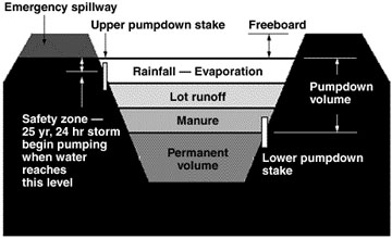 Figure 1
Schematic of volume fractions in manure earthen basin design.
Manure storage pits are designed to contain the waste and wastewater from the livestock facility for the wettest year in 10, plus, the basin must be able to contain a 25-year, 24-hour rainfall event. Manure storage pits are designed with an emergency spillway in the event a rainfall event greater then the 25-year, 24-hour storm occurs. The emergency spillway will protect the berm integrity while controlling where the overflow from the runoff event goes.
Additional design guidelines for earthen pits may be found in Missouri DNR's publication 10 CSR 20-8.020, Design of Small Sewage Works, under Waste Water Stabilization Ponds, and NRCS's Standard and Specification number 425 for Waste Storage Ponds.
Table 1 gives typical pit sizes for various herd sizes in Missouri. These values are averages only and should not be used in lieu of a specific design.
Table 1
Typical sizes of earthen dairy waste pits in Missouri, designed for 180 days of storage with no outside lot runoff, 42-inch average annual rainfall, 3:1 slopes.1
| Number milking cows | Pit volume (cubic feet) | Depth (feet) | Waterline dimensions (feet x feet) | Pumpdown (volume, gallons) |
|---|---|---|---|---|
| 50 | 39,000 | 8 | 93 x 93 | 234,000 |
| 100 | 63,000 | 8 | 112 x 112 | 384,000 |
| 150 | 87,000 | 8 | 127 x 127 | 533,000 |
| 200 | 110,000 | 8 | 140 x 140 | 680,000 |
| 300 | 155,000 | 8 | 163 x 163 | 972,000 |
1Capacity included for milking parlor wash water, ranging from 300 gallons per day for 50 cows to 600 gallons per day for 300 cows.
Earthen pit design — shape
Circular or square pits facilitate mixing and are usually more economical to construct. Rectangular pits may be used; length to width ratios of 3:1 or less are recommended. Avoid narrow appendages isolated from the main body of liquid; they contribute little volume and may be a source of nuisance conditions.
Minimum depth should be 8 feet; 8- to 20-foot depths are typical, depending on animal numbers, runoff area, the site's slope, and underground geology. Pits deeper than 8 feet offer these advantages:
- A smaller surface area requiring less land.
- Minimum odors.
- Efficient use of mechanical agitation.
Slopes of earthen dikes and banks usually range from 2:1 to 3:1; approved slopes are 3:1 or less to facilitate establishment of vegetative cover and for safe mowing of the vegetation (4:1 is recommended for the outer slopes). A minimum ten foot top width is recommended.
An emergency spillway shall be provided at a minimum of one foot below the top of the berm after allowance is made for settlement. The emergency spillway should be located as close to natural ground as possible. This spillway is intended only for dam protection in extreme flooding and is not to be used as a spillway in lieu of pumping down the pit.
Construction techniques — sealing
Proper pit construction will ensure that groundwater resources are protected and the pit will perform as required during its useful life. The following steps are included in most guidelines for accepted construction techniques and methods for earthen pits.
Site preparation
All trees, grass and organic matter should be removed from the site. Topsoil should be stockpiled adjacent to the construction site for later placement on the top and exposed slopes to enhance grass establishment. After stripping, the foundation area should be prepared to bond with the fill by removing loose, dry material, scarifying, disking, adjusting moisture and compacting as necessary.
Cutoff trench
A cutoff trench may be required to remove sand, gravel or other water-conducting materials to prevent leakage under the embankment.
Excavation
Rocks, sand lenses, gravel and any material not suitable for sealing should be removed from the impoundment. Excavation sufficient to obtain proper pit volume plus any required over-excavation for seal construction should be accomplished.
Embankments
Pit embankments should be constructed to allow for settlement (usually 5 percent extra for settlement), mowing and erosion prevention. Suitable excavated materials, free of sod, roots, frozen soil, stones more than 6 inches in diameter, or other objectionable material, should be used for the fill. The minimum moisture content of the fill material and foundation should be such that, when kneaded in the hand, the fill material will form a ball that will not readily separate. NRCS requires three passes of a sheepsfoot roller per six-inch fill lift on the embankment.
Seal construction
Earthen pits must have a seal on the bottom and sides sufficiently impermeable to protect groundwater. Seal construction guidelines generally call for over-excavation and recompaction of seal material in lifts not exceeding 6 inches compacted depth (not more than 9 inches deep before compaction). The lower six inches of the bottom seal may be scarified and compacted in place to eliminate removal and replacement. The seal material should be within 2 percent below and 4 percent above the optimum moisture content for compaction. In general, a minimum of a one foot thick clay seal must be provided on the bottom and sides of a lagoon. The deeper the pit, the thicker the required seal, up to 4.63 feet thick for a liquid depth of 25 feet.
A given permeability or leach rate, such as 1 x 10⁻⁷ centimeters per second, is a typical seal construction specification. Compaction of the seal with three passes of a sheepsfoot roller will usually meet this specification if suitable materials and moisture content are present. Soil amendments such as bentonite or soda ash or, in extreme cases, artificial liners, may be required to obtain a proper seal. The pit seal shall be covered with water immediately after construction to prevent drying and cracking of the seal (at least 2 feet above the highest bottom elevation).
Concrete-lined pits
Concrete-lined pits are an option where suitable soil is not available for sealing an earthen pit. Concreting may provide a more aesthetically pleasing appearance and allow the use of steeper side slopes, which decreases the area required per unit of storage volume. Concrete is normally placed in a single pour across the bottom and around the side slopes up to the top of the berms. To simplify construction, (expansion) joints are eliminated by increasing the reinforcing steel to minimize temperature and shrinkage cracking. For a 4-inch thick concrete liner (laid on plastic or sand), number 3 rebar at 9.2 inches on centers each way, or 6 x 6-W6.5 x W6.5 wire mesh, is minimum reinforcement for temperature and shrinkage. A concrete mix with 6.5 bags of cement per cubic yard, 5.5 to 6 gallons of water per bag of cement, 5 to 8 percent entrained air, and 1.5-inch maximum aggregate size is recommended. An alternate specification is to call for a 4,000 PSI mix with 5 to 8 percent air and a maximum 5-inch slump. Typical concrete slopes of 1:1 to 2:1 require the use of a "stiff" mix to prevent the mix from slumping on the steep slopes.
Estimated costs, in 1993 dollars, for lining a typical manure storage basin for a 100-cow dairy herd with concrete are shown in Table 2.
Table 2
Estimated costs (1993 dollars) for lining a typical manure storage basin for a 100-cow dairy herd with concrete
| Assumptions A square earthen basin 8 feet deep plus 1 foot of freeboard with 2:1 inside slopes, 44-inch annual rainfall, 300 gallons per day wash water, 4-inch thick reinforced concrete liner costs $120 per cubic yard in place. | |||
| Runoff | Storage | ||
|---|---|---|---|
| 90 days | 120 days | 180 days | |
| 0 square feet | $9,485 | $11,870 | $16,950 |
| 10,000 square feet | 15,060 | 18,615 | 25,890 |
| 20,000 square feet | 19,665 | 24,035 | 33,005 |
| 30,000 square feet | 24,110 | 29,300 | 39,945 |
Transferring waste to storage
Wastes in the slurry form are usually transferred to the storage basin by scraping or by using a pump designed for semi-solids. Semi-solids may be scraped directly into the basin, usually from a push-off slab, or scraped into a reception pit. Wastes may be drained from the reception pit to the basin by gravity through a large pipe (typically 24 inches or more in diameter) or pumped to the basin by a ram-type or an impeller-type pump. For gravity discharge, liquid wastes from the milking area should be drained to the receptor pit, discharging on the opposite side of the pit from the transfer pipe inlet and slightly above the transfer pipe inlet. A trap should be placed in the line to prevent odors and gases from entering the milkhouse.
Reception pits are usually designed with capacity for one day's waste production; a pit 8-feet long, 4-feet wide and 6-feet deep will serve a 100-cow herd. A depth of 6 feet will usually provide sufficient head to overcome entrance losses at the discharge pipe. At least 6 feet of head from the elevation of the emergency spillway to the reception pit discharge is recommended. Rounded corners and a pit floor slope of at least 10 percent to the discharge pipe helps reduce problems caused by manure building up and drying on pit surfaces. PVC pipe and corrugated plastic pipe with smooth inside surfaces cause less resistance to flow than pipes with rougher surfaces and joints.
Pit inlets
If manure will enter the pit via a pipe or sewer line, the line should enter the pit below the minimum pumpdown level. (Inlets above the liquid surface are susceptible to freezing where exposed at the end.)
The inlet discharge should be located near the center of the longest side of the pit, if possible, or at several locations in large pits, so that solids are distributed and not allowed to accumulate near the edge. Ideally, the pipe should extend to near the center of the pit. One discharge point per acre of pit will avoid large concentrations of solids at one point. Multiple pipe inlets should be fed equally from a distribution box.
All sewer lines should be designed with cleanouts at 50-foot intervals.
Solids exclusion — agitation
Bedding and fibrous material will break down very slowly, or not at all, in a pit. Non-degradable material leads to sludge buildup and/or crusts forming on the surface, both of which require vigorous agitation for removal from the pit during pumping operations. Agitation before and during pumpdown is necessary to allow removal of all the earthen pit contents.
Earthen pits should always be well-agitated to ensure that solids in sludge and/or crusts are removed during pumpdown. Otherwise, the effective volume of the pit will be severely reduced in a short period of time.
Agitation is accomplished by using high-horsepower, propeller-type agitators or recirculation with high-capacity pumps.
Access ramps and pump platforms
Concrete access ramps and pumping/agitation platforms should be provided as needed for all-weather access to the tank for agitating, pumping and/or mechanically removing solids. Ramp slopes should be no steeper that 10:1 for tanker/spreader access and no steeper than 5:1 for tractor/agitator or tractor/pump access. Grooves or ridges 1 inch or more deep across the ramp should be formed into the concrete before it sets to improve traction. Concrete platforms built into the inside slope of earthen pit berms greatly facilitate positioning of pumping and agitating equipment.
Startup — management
Earthen pits should be filled two feet above the highest point of the pit bottom with water before manure is introduced into the pit to prevent cracking of the clay liner.
Pumping operations should be initiated before the pit is full to assure that space (safety volume) is always available to hold the 25-year, 24-hour storm (6 inches in Missouri). The Missouri DNR guidelines call for pumping the pit when the water level is 1 foot or more below the full pool level if the pit is designed for 365 days of storage. If the open-lot surface area contributing to the pit inflow is greater than 70 percent of the pit area, the safety volume depth is computed using the following formula:
| Safety volume depth = | 0.67 feet + | square foot lot surface x 0.5 feet square foot pit liquid surface area |
Refer to Figure 1 to see how the safety volume depth (safety zone) is measured. Permanent markers should be installed at the depth to initiate pumping the pit 1 foot or more below the full pool level) and at the depth at which to stop pumping (2 feet above the highest point in the bottom of clay-lined pits).
Safety and appearance
Efforts should be made to make a pit as aesthetically pleasing in appearance as possible. Earthen berms and embankments should have a good grass cover for appearance and erosion control, and be mowed and maintained on a regular basis. Such practices enhance good access to all parts of the pit as well as improving appearance. If an earthen pit is within public view, a visually screening row of trees may be desirable. A well-maintained pit is less likely to attract attention and cause controversy than a pit with an offensive appearance.
A fence should be provided to prevent access of children, trespassers and livestock to the pit, located to permit mowing the berms. Post warning signs (SEWAGE TREATMENT FACILITY — KEEP OUT) and keep the gate locked.
Under some topographical conditions, a pit may be constructed such that it can be emptied or drained by gravity through a 12-inch or larger pipe into a tankwagon. This approach has a relatively high risk of pollution should there be a failure or improper use of the valve in the discharge pipe. Therefore, this technique generally should not be considered. If a gravity drain is used, it is recommended that a safety valve be included in the gravity drain system to prevent a discharge in the event the main valve used to control the flow in the gravity drain pipe fails.
References
- Missouri Manual 121, Design Guidelines for Animal Waste Management for Concentrated Animal Feeding Operations. Second Edition, July 1989. Missouri Department of Natural Resources — Water Pollution Control Program, P.O. Box 176, Jefferson City, Mo. 65102.