A pond or lake equipped with a bottom-withdrawal spillway will store the highest-quality water possible for a reservoir in a given location. This is desirable when the reservoir will provide water for municipalities, livestock, households, fish production, recreation, field or orchard spraying, trickle irrigation, or other uses requiring high-quality water. The bottom withdrawal spillway discharges most of the muddy inflow, which decreases the sedimentation rate and increases the useful life of a water reservoir. The water discharged will have a higher sediment and nutrient content than water from conventional surface-withdrawal spillways.
Similarities of the bottom-withdrawal spillway
Detention structures with the bottom-withdrawal spillway are designed similarly to those with canopy or hood inlet spillways. The cross-section and construction of the embankment are the same. The procedure for determining the length and diameter of the principal spillway pipe is similar. You use anti-seep collars to increase the path of seepage along the pipe by at least 10 percent.
Alternative design procedures are described in the Natural Resources Conservation Service Engineering Field Manual. In Missouri, the Natural Resources Conservation Service and the Cooperative Extension Service have a micro-computer program to design dams and spillways.
Uniqueness of the bottom-withdrawal spillway
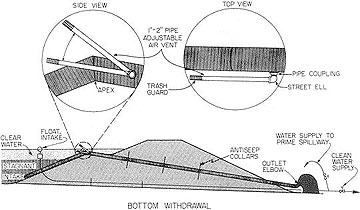
As the name implies, the bottom-withdrawal spillway removes the excess water (caused by storm runoff) from the bottom of the pond (or lake). Locating the discharge pipe inlet below 80 percent of the normal pool depth will usually preserve 96 percent of the clean water stored in the reservoir. Increasing the temporary storage volume (between the principal spillway and the emergency spillway) will decrease the loss of clean water through the emergency spillway.
The other advantage of having a deep intake is that few fish will be lost when it is located deeper than 8 feet because the deeper water is usually anoxic (without oxygen) during the warm months. This eliminates the need to fence in the fish. In addition, inlet clogging from floating debris is no longer a problem.
The outlet elbow, also unique to this spillway design, enhances the operational versatility of the spillway. It serves as an airlock, so siphoning begins at a lower water level. If the air vent is submerged, water turbulence in the pipe will entrain air and remove it from the pipe, causing siphoning until air enters the vent. Second, it serves as an excellent energy dissipater, preventing a deep "plunge pool." Third, it aerates the anoxic bottom water as it leaves the spillway.
Spillway design
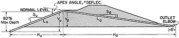
You can proceed with spillway design after you have determined the water elevation, dam cross-section, and desired spillway discharge rate. Determine the required length of pipe graphically by plotting the dam cross-section and then scaling the length of pipe needed. An alternative method is to calculate the length, first by summing the net horizontal and vertical distances of each pipe and then by calculating the two diagonal lengths:
Total length = Lu + Ld = (Hu2 + Vu2)0.5 + (Hd2 + Vd2)0.5
where
Lu = length of pipe upstream (from the apex),
Ld = length of pipe downstream, Hu and Hd are the horizontal distances of the upstream and downstream pipes, respectively, and Vu and Vd are, likewise, the vertical distances upstream and downstream, respectively.
The upstream and downstream pipes connect to form the apex (bend) angle. This angle, or bend in the pipe, should be calculated if you use a prefabricated miter bend.
Compute the bend angle (at the apex) from the slopes of the two sections of pipe by the equation:
Bend angle = tan-1(Vu/Hu) + tan-1(Vd/Hd)= tan-1(1/Su) + tan-1(1/Sd)
To construct the miter bend, cut the pipe at one-half the bend angle, roll the cut-off piece 180 degrees and then weld the pieces back together to form the bend. This miter bend may vary from 27 to 35 degrees (deflection angle). For example, if the slope of the upstream pipe is 2.5 to 1 and the slope of the downstream pipe is 7 to 1 (through the dam), the bend angle would be 30 degrees (21.8 + 8.1). You would cut the ends of the pipe at 15 degrees to form the 30-degree miter bend. If you use plastic pipe, one or two 22.5-degree elbows can be used to obtain the proper angle.
Table 1. Pipe flow rates in CFS.
Using Bernoulli's equation: Q = A(64.4H)0.5/(1 + Km + KpL)0.5.
Pipe flow for smooth steel pipe, n = 0.013, Km = Ke + Kb + Kelbow = 1.1 and length = 100 feet
| H, Head | Nominal diameter of pipe of inches | ||||||||||||
|---|---|---|---|---|---|---|---|---|---|---|---|---|---|
| 4 | 6 | 8 | 10 | 12 | 14 | 16 | 18 | 20 | 22 | 24 | 30 | 36 | |
| Pipe diameter used in calculating flow rate | |||||||||||||
| 4 | 6 | 8 | 10 | 12 | 13.5 | 15.5 | 17.5 | 19.5 | 21.5 | 23.5 | 29.4 | 35.4 | |
| 5 feet | 0.4 | 1.1 | 2.3 | 4 | 6 | 8 | 11 | 15 | 19 | 24 | 29 | 48 | 73 |
| 6 feet | 0.4 | 1.2 | 2.5 | 4 | 7 | 9 | 12 | 16 | 21 | 26 | 32 | 53 | 79 |
| 7 feet | 0.5 | 1.3 | 2.7 | 5 | 7 | 10 | 13 | 18 | 23 | 28 | 35 | 57 | 86 |
| 8 feet | 0.5 | 1.4 | 2.9 | 5 | 8 | 10 | 14 | 19 | 24 | 30 | 37 | 61 | 92 |
| 9 feet | 0.5 | 1.5 | 3.1 | 5 | 8 | 11 | 15 | 20 | 26 | 32 | 39 | 65 | 97 |
| 10 feet | 0.6 | 1.6 | 3.2 | 6 | 9 | 12 | 16 | 21 | 27 | 34 | 41 | 68 | 103 |
| 11 feet | 0.6 | 1.6 | 3.4 | 6 | 9 | 12 | 17 | 22 | 28 | 36 | 43 | 72 | 108 |
| 12 feet | 0.6 | 1.7 | 3.5 | 6 | 10 | 13 | 17 | 23 | 30 | 37 | 45 | 75 | 112 |
| 13 feet | 0.6 | 1.8 | 3.7 | 6 | 10 | 13 | 18 | 24 | 31 | 39 | 47 | 78 | 117 |
| 14 feet | 0.7 | 1.9 | 3.8 | 7 | 10 | 14 | 19 | 25 | 32 | 40 | 49 | 81 | 121 |
| 15 feet | 0.7 | 1.9 | 4.0 | 7 | 11 | 14 | 20 | 26 | 33 | 42 | 51 | 84 | 126 |
| 16 feet | 0.7 | 2.0 | 4.1 | 7 | 11 | 15 | 20 | 27 | 34 | 43 | 52 | 86 | 130 |
| 17 feet | 0.7 | 2.0 | 4.2 | 7 | 11 | 15 | 21 | 28 | 35 | 44 | 54 | 89 | 134 |
| 18 feet | 0.7 | 2.1 | 4.3 | 8 | 12 | 15 | 21 | 28 | 36 | 45 | 56 | 92 | 138 |
| 19 feet | 0.8 | 2.2 | 4.5 | 8 | 12 | 16 | 22 | 29 | 37 | 47 | 57 | 94 | 141 |
| 20 feet | 0.8 | 2.2 | 4.6 | 8 | 12 | 16 | 23 | 30 | 38 | 48 | 59 | 97 | 145 |
| 21 feet | 0.8 | 2.3 | 4.7 | 8 | 13 | 17 | 23 | 31 | 39 | 49 | 60 | 99 | 149 |
| 22 feet | 0.8 | 2.3 | 4.8 | 8 | 13 | 17 | 24 | 31 | 40 | 50 | 62 | 101 | 152 |
| 23 feet | 0.8 | 2.4 | 4.9 | 8 | 13 | 17 | 24 | 32 | 41 | 51 | 63 | 104 | 156 |
| 24 feet | 0.9 | 2.4 | 5.0 | 9 | 13 | 18 | 25 | 33 | 42 | 53 | 64 | 106 | 159 |
| 25 feet | 0.9 | 2.5 | 5.1 | 9 | 14 | 18 | 25 | 33 | 43 | 54 | 66 | 108 | 162 |
| 26 feet | 0.9 | 2.5 | 5.2 | 9 | 14 | 19 | 26 | 34 | 44 | 55 | 67 | 110 | 165 |
| 27 feet | 0.9 | 2.6 | 5.3 | 9 | 14 | 19 | 26 | 35 | 45 | 56 | 68 | 112 | 169 |
| 28 feet | 0.9 | 2.6 | 5.4 | 9 | 15 | 19 | 27 | 35 | 45 | 57 | 69 | 114 | 172 |
| 29 feet | 1.0 | 2.7 | 5.5 | 10 | 15 | 20 | 27 | 36 | 46 | 58 | 71 | 116 | 175 |
| 30 feet | 1.0 | 2.7 | 5.6 | 10 | 15 | 20 | 28 | 37 | 47 | 59 | 72 | 118 | 178 |
| L | Correction factors for other pipe lengths | ||||||||||||
| 50 feet | 1.33 | 1.29 | 1.25 | 1.22 | 1.19 | 1.18 | 1.16 | 1.14 | 1.13 | 1.12 | 1.11 | 1.09 | 1.07 |
| 60 feet | 1.24 | 1.21 | 1.18 | 1.16 | 1.15 | 1.14 | 1.12 | 1.11 | 1.10 | 1.09 | 1.09 | 1.07 | 1.06 |
| 70 feet | 1.16 | 1.14 | 1.13 | 1.12 | 1.10 | 1.10 | 1.09 | 1.08 | 1.07 | 1.07 | 1.06 | 1.05 | 1.04 |
| 80 feet | 1.10 | 1.09 | 1.08 | 1.07 | 1.07 | 1.06 | 1.06 | 1.05 | 1.05 | 1.04 | 1.04 | 1.03 | 1.03 |
| 90 feet | 1.05 | 1.04 | 1.04 | 1.03 | 1.03 | 1.03 | 1.03 | 1.02 | 1.02 | 1.02 | 1.02 | 1.02 | 1.01 |
| 100 feet | 1.00 | 1.00 | 1.00 | 1.00 | 1.00 | 1.00 | 1.00 | 1.00 | 1.00 | 1.00 | 1.00 | 1.00 | 1.00 |
| 110 feet | 0.96 | 0.96 | 0.97 | 0.97 | 0.97 | 0.97 | 0.98 | 0.98 | 0.98 | 0.98 | 0.98 | 0.98 | 0.99 |
| 120 feet | 0.92 | 0.93 | 0.94 | 0.94 | 0.95 | 0.95 | 0.95 | 0.96 | 0.96 | 0.96 | 0.96 | 0.97 | 0.97 |
| 130 feet | 0.89 | 0.90 | 0.91 | 0.91 | 0.92 | 0.93 | 0.93 | 0.94 | 0.94 | 0.94 | 0.95 | 0.96 | 0.96 |
| 140 feet | 0.86 | 0.87 | 0.88 | 0.89 | 0.90 | 0.90 | 0.91 | 0.92 | 0.92 | 0.93 | 0.93 | 0.94 | 0.95 |
| 150 feet | 0.84 | 0.85 | 0.86 | 0.87 | 0.88 | 0.88 | 0.89 | 0.90 | 0.91 | 0.91 | 0.92 | 0.93 | 0.94 |
| 160 feet | 0.81 | 0.82 | 0.84 | 0.85 | 0.86 | 0.87 | 0.87 | 0.88 | 0.89 | 0.90 | 0.90 | 0.92 | 0.93 |
| 170 feet | 0.79 | 0.80 | 0.82 | 0.83 | 0.84 | 0.85 | 0.86 | 0.87 | 0.87 | 0.88 | 0.89 | 0.91 | 0.92 |
| 180 feet | 0.77 | 0.78 | 0.80 | 0.81 | 0.82 | 0.83 | 0.84 | 0.85 | 0.86 | 0.87 | 0.88 | 0.89 | 0.91 |
| 190 feet | 0.75 | 0.76 | 0.78 | 0.79 | 0.81 | 0.82 | 0.83 | 0.84 | 0.85 | 0.86 | 0.86 | 0.88 | 0.90 |
| 200 feet | 0.73 | 0.75 | 0.76 | 0.78 | 0.79 | 0.80 | 0.81 | 0.82 | 0.83 | 0.84 | 0.85 | 0.87 | 0.89 |
| 210 feet | 0.72 | 0.73 | 0.75 | 0.76 | 0.78 | 0.79 | 0.80 | 0.81 | 0.82 | 0.83 | 0.84 | 0.86 | 0.88 |
| 220 feet | 0.70 | 0.72 | 0.73 | 0.75 | 0.76 | 0.77 | 0.79 | 0.80 | 0.81 | 0.82 | 0.83 | 0.85 | 0.87 |
Spillway discharge
The discharge through the spillway is affected by the pipe's diameter, length and roughness, and minor losses such as entrance, miter bend and discharge elbow losses. You can estimate the discharge from Table 1 or 2. If you use the previous example and assume Vu = Vd = 15 feet, then LU = 37.5 feet, Ld = 105 feet, and L = 142.5 feet. From Table 1, the discharge for a 6-inch smooth steel pipe (n = 0.013) with 15 feet of head would be 1.9 cfs (cubic feet per second) for 100 feet of pipe. The correction factor for 142.5 feet of pipe is 0.865 (by interpolation). Therefore, the discharge for 142.5 feet of 6-inch pipe is 1.9 x 0.865 = 1.64 cfs. If you need a larger discharge, you should select a larger pipe diameter. If you encounter conditions other than those assumed in Tables 1 and 2, refer to the following section, "Formulas for special cases," to compute the discharge.
Table 2. Pipe flow rates in CFS.
Using Bernoulli's equation: Q = A(64.4H)0.5/(1 + Km + KpL)0.5.
Pipe flow for corrugated pipe, n = 0.025, Km = Ke + Kb + Kelbow = 1.1 and length = 100 feet.
| H, Head | Nominal diameter of pipe in inches | |||||||||
|---|---|---|---|---|---|---|---|---|---|---|
| 6 | 8 | 10 | 12 | 15 | 18 | 21 | 24 | 30 | 36 | |
| Pipe diameter used in calculating flow rate | ||||||||||
| 6 | 8 | 10 | 12 | 15 | 18 | 21 | 24 | 30 | 36 | |
| 5 feet | 0.6 | 1.3 | 2 | 4 | 7 | 11 | 16 | 22 | 37 | 58 |
| 6 feet | 0.7 | 1.5 | 3 | 4 | 7 | 12 | 17 | 24 | 41 | 63 |
| 7 feet | 0.7 | 1.6 | 3 | 4 | 8 | 13 | 18 | 26 | 44 | 68 |
| 8 feet | 0.8 | 1.7 | 3 | 5 | 8 | 13 | 20 | 27 | 47 | 73 |
| 9 feet | 0.8 | 1.8 | 3 | 5 | 9 | 14 | 21 | 29 | 50 | 78 |
| 10 feet | 0.9 | 1.9 | 3 | 5 | 9 | 15 | 22 | 31 | 53 | 82 |
| 11 feet | 0.9 | 2.0 | 4 | 6 | 10 | 16 | 23 | 32 | 55 | 86 |
| 12 feet | 1.0 | 2.1 | 4 | 6 | 10 | 16 | 24 | 34 | 58 | 90 |
| 13 feet | 1.0 | 2.1 | 4 | 6 | 11 | 17 | 25 | 35 | 60 | 93 |
| 14 feet | 1.1 | 2.2 | 4 | 6 | 11 | 18 | 26 | 36 | 63 | 97 |
| 15 feet | 1.1 | 2.3 | 4 | 7 | 12 | 18 | 27 | 38 | 65 | 100 |
| 16 feet | 1.1 | 2.4 | 4 | 7 | 12 | 19 | 28 | 39 | 67 | 104 |
| 17 feet | 1.2 | 2.5 | 4 | 7 | 12 | 20 | 29 | 40 | 69 | 107 |
| 18 feet | 1.2 | 2.5 | 5 | 7 | 13 | 20 | 30 | 41 | 71 | 110 |
| 19 feet | 1.2 | 2.6 | 5 | 7 | 13 | 21 | 30 | 42 | 73 | 113 |
| 20 feet | 1.3 | 2.7 | 5 | 8 | 13 | 21 | 31 | 43 | 75 | 116 |
| 21 feet | 1.3 | 2.7 | 5 | 8 | 14 | 22 | 32 | 45 | 77 | 119 |
| 22 feet | 1.3 | 2.8 | 5 | 8 | 14 | 22 | 33 | 46 | 78 | 121 |
| 23 feet | 1.3 | 2.9 | 5 | 8 | 14 | 23 | 34 | 47 | 80 | 124 |
| 24 feet | 1.4 | 2.9 | 5 | 8 | 15 | 23 | 34 | 48 | 82 | 127 |
| 25 feet | 1.4 | 3.0 | 5 | 8 | 15 | 24 | 35 | 49 | 84 | 129 |
| 26 feet | 1.4 | 3.0 | 5 | 9 | 15 | 24 | 36 | 50 | 85 | 132 |
| 27 feet | 1.5 | 3.1 | 6 | 9 | 16 | 25 | 36 | 50 | 87 | 134 |
| 28 feet | 1.5 | 3.2 | 6 | 9 | 16 | 25 | 37 | 51 | 89 | 137 |
| 29 feet | 1.5 | 3.2 | 6 | 9 | 16 | 26 | 38 | 52 | 90 | 139 |
| 30 feet | 1.5 | 3.3 | 6 | 9 | 16 | 26 | 38 | 53 | 92 | 142 |
| L | Correction factors for other pipe lengths | |||||||||
| 50 feet | 1.37 | 1.35 | 1.33 | 1.32 | 1.29 | 1.27 | 1.25 | 1.23 | 1.20 | 1.18 |
| 60 feet | 1.26 | 1.25 | 1.24 | 1.23 | 1.21 | 1.20 | 1.19 | 1.17 | 1.15 | 1.14 |
| 70 feet | 1.18 | 1.17 | 1.16 | 1.16 | 1.15 | 1.14 | 1.13 | 1.12 | 1.11 | 1.10 |
| 80 feet | 1.11 | 1.10 | 1.10 | 1.10 | 1.09 | 1.09 | 1.08 | 1.08 | 1.07 | 1.06 |
| 90 feet | 1.05 | 1.05 | 1.05 | 1.05 | 1.04 | 1.04 | 1.04 | 1.04 | 1.03 | 1.03 |
| 100 feet | 1.00 | 1.00 | 1.00 | 1.00 | 1.00 | 1.00 | 1.00 | 1.00 | 1.00 | 1.00 |
| 110 feet | 0.96 | 0.96 | 0.96 | 0.96 | 0.96 | 0.96 | 0.97 | 0.97 | 0.97 | 0.97 |
| 120 feet | 0.92 | 0.92 | 0.92 | 0.92 | 0.93 | 0.93 | 0.93 | 0.94 | 0.94 | 0.95 |
| 130 feet | 0.88 | 0.89 | 0.89 | 0.89 | 0.90 | 0.90 | 0.91 | 0.91 | 0.92 | 0.93 |
| 140 feet | 0.85 | 0.86 | 0.86 | 0.86 | 0.87 | 0.88 | 0.88 | 0.89 | 0.90 | 0.90 |
| 150 feet | 0.83 | 0.83 | 0.83 | 0.84 | 0.84 | 0.85 | 0.86 | 0.86 | 0.87 | 0.88 |
| 160 feet | 0.80 | 0.81 | 0.81 | 0.81 | 0.82 | 0.83 | 0.84 | 0.84 | 0.85 | 0.87 |
| 170 feet | 0.78 | 0.78 | 0.79 | 0.79 | 0.80 | 0.81 | 0.81 | 0.82 | 0.84 | 0.85 |
| 180 feet | 0.76 | 0.76 | 0.77 | 0.77 | 0.78 | 0.79 | 0.80 | 0.80 | 0.82 | 0.83 |
| 190 feet | 0.74 | 0.74 | 0.75 | 0.75 | 0.76 | 0.77 | 0.78 | 0.79 | 0.80 | 0.82 |
| 200 feet | 0.72 | 0.72 | 0.73 | 0.74 | 0.74 | 0.75 | 0.76 | 0.77 | 0.79 | 0.80 |
| 210 feet | 0.70 | 0.71 | 0.71 | 0.72 | 0.73 | 0.74 | 0.75 | 0.75 | 0.77 | 0.79 |
| 220 feet | 0.69 | 0.69 | 0.70 | 0.70 | 0.71 | 0.72 | 0.73 | 0.74 | 0.76 | 0.77 |
Air vent
The primary purpose of the air vent is to stop the siphoning flow of the spillway when the water level reaches the desired level. The air vent can be fixed (for example, a hole in the apex of the pipe) or adjustable (for example, a short piece of pipe can be attached to the hole so that the pipe can rotate around the hole). The air vent is normally near the apex and above the normal pool level. You can make the air vent movable by using a threaded elbow, a union and an elbow, a friction-fit plastic elbow, or flexible tubing that will not collapse under a partial vacuum.
The diameter of the air vent should be at least 1/14 (7 percent) of the spillway pipe diameter. Protect the air vent opening by attaching a screen to it or placing it in a screened enclosure to prevent plugging by leaves, nuts or fish.
Modification of existing spillways
- You can easily convert hood and canopy spillways into bottom-withdrawal spillways. First, survey the upstream slope of the dam, from the existing pipe to the deepest point, to determine the length of pipe needed. Check to see whether it can be straight or if it will require another bend.
- Bring the appropriate amount of pipe to the site and assemble it near the water's edge. This pipe should be the same size as the existing pipe. If the same size is unavailable, use a slightly larger size if you can make the connection to the existing pipe.
- Remove the existing hood or canopy and miter the existing pipe at the appropriate angle. If you add corrugated metal pipe to existing smooth or corrugated metal pipe, you can weld a short 2-foot section (mitered at the appropriate angle) to the existing pipe. To this short section, clamp the longer upstream section with a water-tight clamp. (An alternative method to join corrugated metal pipe to an existing corrugated metal pipe spillway follows: Cut the end off the existing pipe with a square cut to allow clamping on a prefabricated miter bend to position the apex as desired. The prefab miter bend may be re-galvanized for long life.)
- Float the new section of pipe into place by temporarily plugging the intake end and rolling the pipe into the water. Don't allow the apex end to enter the water. Hold it near the existing pipe with a chain or cable. When the pipe is properly positioned, remove the temporary plug and allow the pipe to settle into place. Pull the apex into final position so you can weld or caulk it and clamp it to the existing pipe to make an airtight connection.
- Complete the modification by adding the air vent and the outlet elbow.
Summary
New ponds, as well as existing ponds, can be easily equipped with a bottom-withdrawal spillway system. The design of this spillway is similar to that of other spillway pipes. First, determine the elevations and physical layout. Then determine the pipe diameter needed for the required flow capacity. You can convert existing hood and canopy spillways to bottom-withdrawal spillways. By installing bottom-withdrawal spillways, ponds and reservoirs will last longer and provide clean water for many years to come.
Formulas for special cases
For pipes with more than one miter bend or for a spillway with a bell-shaped entrance, you can more accurately calculate the discharge by using Bernoulli's equation:
Q = 8.025(A)(H)0.5 ÷(1 + Km + KpL)0.5
where
Q = discharge in cfs
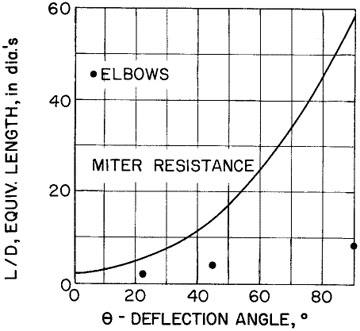
Other minor friction losses in this spillway are caused by bends at the apex angle and the outlet elbow. Since this loss is dependent upon the roughness of the elbow or bend, it is easier (and more accurate) to calculate this loss as an equivalent length of pipe that is added to the actual total length of pipe before it is multiplied by Kp in the above equation.
The apex angle head losses are usually quite small since the angle will normally be from 27 to 35 degrees deflection. The losses for elbows that might be used for the apex angle of plastic pipe are also shown.
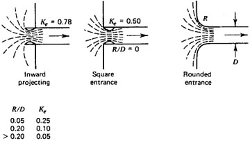
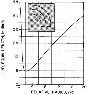
You can treat the outlet elbow in a similar fashion. You can keep the loss to a minimum if the relative radius, r/d, equals 2. The equivalent length, L/D, times the diameter in feet gives the equivalent length of pipe (in feet) to be added to the pipe's actual total length.
The head loss coefficients for circular pipes (Table 3) are multiplied by the sum of the actual pipe length plus the equivalent lengths caused by bends in the pipe.
If you join two kinds of pipe with different n values to fabricate the spillway, compute the modified flow rate, Qm in cfs, by the following equation:
Qm = 8.025(A)(H)0.5/(1 + Km + KnpLn + KopLo)0.5