Storage structures for liquid dairy waste range from low-cost earthen basins and moderate-cost concrete tanks to higher-cost, glass-lined steel tanks. Figure 1 shows a cost comparison for some typical structures. Due to the high cost of storage volume, tanks are not usually used to contain lot runoff. Tanks offer an alternative for waste storage in areas with karst terrain, where the site is rated as having a severe collapse potential and an earthen pit will not be approved. This publication deals with concrete and steel tanks but not with concrete pits under buildings.
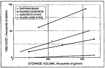 Figure 1
Comparative costs for various manure storage structures.
Tanks may be located above grade, below, or partially below grade. Below-grade tanks are easy to fill by scraping whereas above-grade tanks may require pumps for filling. Open storage structures should be located to minimize odor and sight nuisances, but they should be located as convenient to the source of waste as practicalli.. Tanks should be located at least 100 feet from water wells. Open tanks should be fenced, as necessary, to exclude animals and children. Tanks filled by scraping should have guard rails or grates to prevent machinery from entering the tank, as well as animals and people.
Tank design — size (volume)
Manure tanks are sized by volume. Proper design, or sizing, of a tank ensures that sufficient volume is available for the required storage period. The minimum recommended storage period before the tank must be pumped down, is 120 days. The MU College of Agriculture, Food and Natural Resources has a computer program (Number AG003) for tank (and lagoon) design that may be purchased for nominal cost. The total volume (size) of a tank is composed of several volume fractions as explained below.
Residual volume
This fraction of the tank volume consists of a 6- to 12-inch depth at the bottom of the tank that normally cannot be pumped out if the tank has no sump.
Manure storage volume
This fraction of the tank volume provides storage for the volume of manure the tank will receive during the design storage period, and is removed when the tank is pumped. Storage periods usually range from 3 to 6 months, with longer storage periods offering greater flexibility in scheduling pumping operations.
Wash water volume and other sources
This fraction of the tank volume provides storage for any wash water or other fresh water used for cleaning buildings or lot areas and, infrequently, for runoff from open lots during the design storage period. It is important to minimize the area draining into the tank to prevent unnecessary pumpout and to reduce the required tank size (cost). Wash water and runoff from lots can be stored at much lower cost in a lagoon.
Volume components affected by rainfall (runoff volume and rainfall/evaporation volume) must be determined based on the wettest year in 10 years for DNR approval. Runoff from roofs and concrete lots for the wettest year out of 10 ranges from 2.9 feet per year in northwest Missouri to 4.2 feet per year in southeast Missouri.
Net rainfall/evaporation on the tank surface
This fraction of the tank volume provides storage for the net gain of rainfall over evaporation on the surface of open-top tanks. For the wettest year out of 10, the rainfall minus evaporation varies from about 0.9 feet per year in northwest Missouri to 2.5 feet per year in southeast Missouri (Ref. Table 4 in Missouri Manual 121, Missouri Department of Natural Resources.).
Safety volume depth
Pumping operations should be initiated before the tank is full to assure that space (safety volume) is always available to hold the 25-year, 24 hour storm (6 inches in Missouri). The DNR guidelines call for pumping the tank when the water level is 1 foot or more below the full pool level, if minimal open lot area contributes input to the tank. This allows for the recommended 6 inches of freeboard if a 6-inch storm occurs when the liquid level is one foot below the top of the tank.
If the open-lot surface area contributing to the pit inflow is greater than 70 percent of the tank area, the safety volume depth is computed using the following formula:
| Safety volume depth = | 0.67 + | square feet lot surface x 0.5 feet sq. feet tank liquid surface area |
Figure 2 shows the volume fractions considered in the design of dairy waste tanks in Missouri.
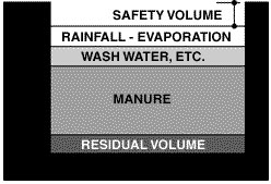 Figure 2
Schematic of volume fractions in manure tank design.
Table 1 lists typical tank sizes for various herd sizes in Missouri. These values are averages only and should not be used in lieu of a specific design.
Table 1
Typical sizes of open-top dairy waste tanks receiving no wash water or outside lot runoff in an area of Missouri with 42-inch average annual rainfall, with allowance for a total of 18 percent dilution water to facilitate agitation and pumping, 120-day storage period. Assumes 6-inch freeboard at top of tank and 6-inch depth at bottom that can't be pumped out (volume gallons does not include these two 6-inch depths)
| Number of milking cows | Volume (gallons) | 8-foot deep tank diameter (feet) | 14-foot deep tank diameter (feet) |
|---|---|---|---|
| 50 | 98,400 | 50 | 36 |
| 100 | 196,800 | 69 | 51 |
| 150 | 295,200 | 85 | 62 |
| 200 | 393,600 | 98 | 72 |
| 300 | 590,400 | 120 | 88 |
Tank depths from 8 to 20 feet are typical. Deep tanks offer the following advantages.
- A smaller surface area requiring less space.
- Minimum odors.
- Efficient use of mechanical agitation.
Tank design — structural
The interior hydrostatic wall pressure for structural design is 60 pounds per foot2 per foot. Design loads on the exterior of walls consist primarily of lateral earth pressures, surcharge pressures and hydrostatic pressures. Earth pressures vary with backfill soil type and compaction, with equivalent fluid pressures ranging from 30 to 115 pounds per foot2 per foot. Where heavy equipment may operate within 5 feet of the wall, the wall should be designed for a minimum additional 100 pounds per foot2 surcharge pressure uniformly distributed over the exterior wall height. Exterior hydrostatic pressures vary with the water table level and degree of drainage. Tank covers must be designed for dead loads, and equipment and livestock loads, if applicable.
Concrete tanks
Design guidelines for tanks can be found in ASAE EP393.1, Structures and Environment Handbook. The following design criteria are taken from these publications:
Concrete tank design should conform to the American Concrete Institute's Building Code for Reinforced Concrete (ACI 318). Inward and/or outward forces on tank walls, especially on non-circular tanks, requires the design of highly-reinforced, costly walls. To minimize the required wall section for the top of straight concrete walls that have no support for outward or inward deflection, a common practice is to cast a thickened section at the top of the wall or to cast an integral, outward slab to greatly increase the section modules. On circular concrete-stave tanks, steel hoops are sized and/or spaced to withstand the higher pressures at the bottom of the wall. Typical concrete tank heights range from 8 to 16 feet.
Glass-lined steel tanks
Glass-lined steel tanks are usually purchased from a company which provides a tank designed to withstand the 60 pounds per foot2 per foot hydrostatic load imposed by the contained liquid, and exterior wind loads. Steel tanks should conform to the American Institute of Steel Construction Specifications for the Design, Fabrication, and Erection of Structural Steel for Steel Buildings. Typical steel tank depths range from 10 to 25 feet.
Transferring waste to storage
Wastes in the slurry form are usually transferred to storage tanks by scraping or by using a pump designed for semi-solids. Semi-solids may be scraped directly into the tank, usually from a push-off slab, or scraped into a reception pit and pumped into the storage tank.
Reception pits are usually designed with capacity for one day's waste production; a pit 8 feet long, 4 feet wide and 6 feet deep will serve a 100-cow herd.
Reception pits receiving lot runoff must be equipped with automatic pumping units to prevent an overflow of the reception pit during a rainfall event.
Agitation
Bedding and fibrous material will break down very slowly, or not at all in a tank. Non-degradable material leads to sludge buildup and/or crusts forming on the surface, both of which require vigorous agitation in order to properly pump out the tank. Agitation during pumpdown is advised to eliminate sludge and solids settling during pumpdown. Agitation is accomplished by using high-horsepower, propeller-type agitators or recirculation with high-capacity pumps.
Access ramps
Access ramps, slabs, and pumping/agitation platforms should be provided as needed for all-weather access to the tank with agitating, pumping and/or hauling equipment. Ramps should be no steeper than 5:1 for tractor/pump or tractor/agitator access. Grooves or ridges one inch or more deep across the ramp should be formed into the concrete before it sets to improve traction.
Startup, management
Tanks should be filled with at least 6 inches of water before manure is introduced into the tank to prevent drying of the manure.
Pumping operations should be initiated before the tank is full to assure space (safety volume) is always available to hold the 25-year, 24 hour storm (6 inches in Missouri). The DNR guidelines call for pumping the tank when the water level is one foot or more below the full pool level (safety-volume depth).
Safety and appearance
Efforts should be made to make storage structures as aesthetically pleasing in appearance as possible. Grassed areas should be mowed and maintained on a regular basis. If a tank is within public view, a visually screening row of trees may be desirable. A well-maintained facility is less likely to attract attention and cause controversy than a facility with an offensive appearance.
A fence should be constructed and maintained to prevent access of children, trespassers and livestock to open-top tanks. Post warning signs (SEWAGE TREATMENT FACILITY — KEEP OUT) and keep the gate locked.
Note
Extreme caution should be exercised if a person enters a storage tank that has contained dairy waste to prevent death by asphyxiation from lack of oxygen and/or the presence of lethal gases
If it is absolutely necessary to enter a manure storage tank or pit, OSHA regulations require the use of specialized safety equipment such as a supplied air respirator, which supplies grade D breathing air, or a self-contained breathing apparatus must be used by those who are trained and familiar with the use of this equipment. The person(s) entering the tank or pit should wear rescue harness with a rope to persons outside the tank with a block and tackle to extricate the victim in an emergency.
References
- Missouri Manual 121, Design Guidelines for Animal Waste Management for Concentrated Animal Feeding Operations, Second Edition, July 1989. Missouri Department of Natural Resources — Water Pollution Control Program, P.O. Box 176, Jefferson City, Mo. 65102.
- Building Code for Reinforced Concrete (ACI 318), American Concrete Institute, Detroit, Mich.
- Specifications for the Design, Fabrication, and Erection of Structural Steel for Steel Buildings, American Institute of Steel Construction, New York, N.Y.
- ASAE Engineering Practice: ASAE EP393.1. Manure Storages. ASAE Standards, 1991. St. Joseph, Mich.